|
To borrow a title from a former chancellor of our alma mater; in this post we'll provide a paraphrased history of the project from inception to the present day. Intro and early days Getting straight into it - the idea for the project came from a conversation between Tom M & Tom A at a friends' wedding in 2014 - thanks Andy and Michelle!
 The first 'bat drone' During the project we've been very fortunate to be invited to the Natural History Museum to give a talk and have a stand at a couple of events. One of the questions that comes up most often is "what company or university are you at?" We're not. The project is simply a very enjoyable hobby. We want to help further bat conservation it's a great way that we can assist with this using our respective skills. Tom A is our bat expert (and is now a qualified and competent drone pilot) and Tom M is our drone designer, builder and operator. We think this goes to show that if people are willing, you don't need the support of a big research grant or institution to push boundaries. Our advice is to "give it a go and see where it takes you".
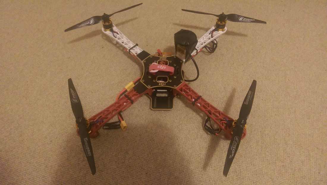
We knew that quadcopters produced a lot of sound but didn't know how much of this was ultrasound. Our first tests showed us that it was a considerable amount. This ultrasonic interference has been a running theme through the project. The problem lies in the signal to noise ratio of the bat call. If there is too much noise from the drone we won't be able to 'hear' the bat call. This meant that we had to separate the drone and the detector recording the bat calls by about five meters. The highly technical application of a piece of string was employed though this wasn't without it's problems as you can see in the video below. The problem of the oscillation arose due to the high weight of the detector. We were glad we used a water bottle of the same weight as the detector in testing! The detector and recorder weighed about a third of the quadcopter mass. This led to loss of control and meant and it wasn't an option in this configuration.
In going back to the drawing board we wanted something that produced less noise and could comfortably fly with the payload of the detector. The obvious choice for us was to move to a plane; it had the added bonus of being able to fly for longer too (about 8 mins for the quad and 25 for the plane).
0 Comments
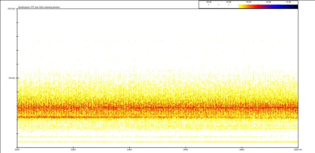
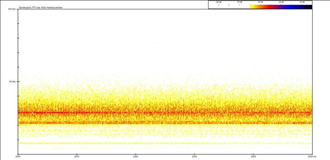
The Talon is one of our two current options for flying bat drones (the other being the quad, see here). It's a small plane which, like the quad, can carry a small bat detector and acoustically record bat calls. Have a look at the first post on it here for more info. One of the major issues we've faced with acoustic monitoring is noise from the propellers. We found that if the detector is not carefully positioned a certain distance from the propeller/s then the noise may drown out any bat calls. This is the latest post in a long line about noise, see the rest of them here. Last blog post about the Talon we looked at a number of different positions of the detector and discovered that about 15cm from the nose is the quietest position we tested. This led to us considering an extended option for the Talon - which is to say, having a stick pointing forwards off the front of the aircraft that the detector is attached to. And it looks like this: 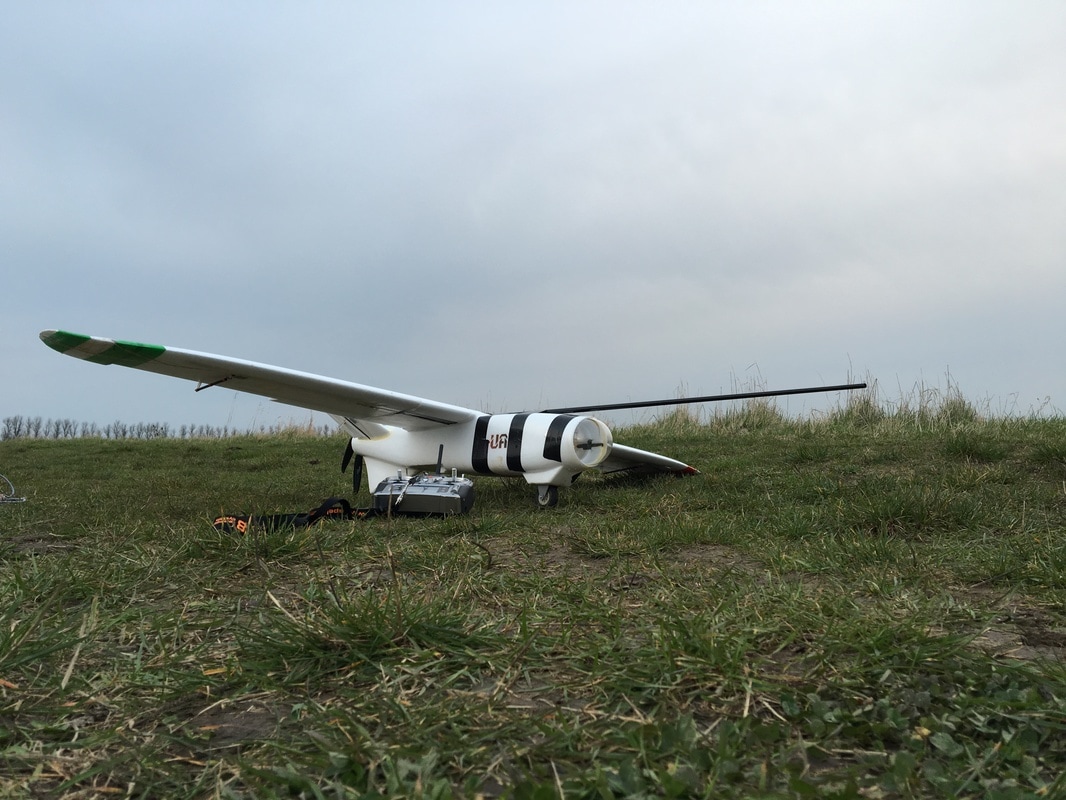 Talon with extension #1 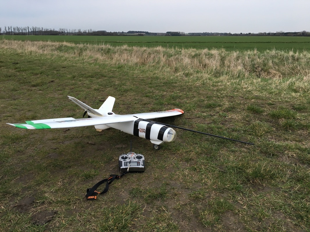 Talon with extension #2 We've secured a glass fibre tube from a fishing rod onto the front of the plane. This increases the distance between the detector and the propeller (the source of the noise). As it's ultrasound, it attenuates quickly so a small increase in distance can lead to a large drop in noise. Oddly, we found during the initial noise testing that the closer position (5cm from the nose) was actually quieter than the further position (15cm from the nose). We're not sure why and would hypothesise it's something to do with the airframe blocking the noise at 5cm. The next stage of testing performed was actually flying with this setup and seeing how our two detectors perform (the Peersonic and the AudioMoth). For interest, we tested the noise levels of the two detectors at two distances from the nose of the plane, 15cm and 50cm (the furthest possible distance). Here's how the noise testing turned out:
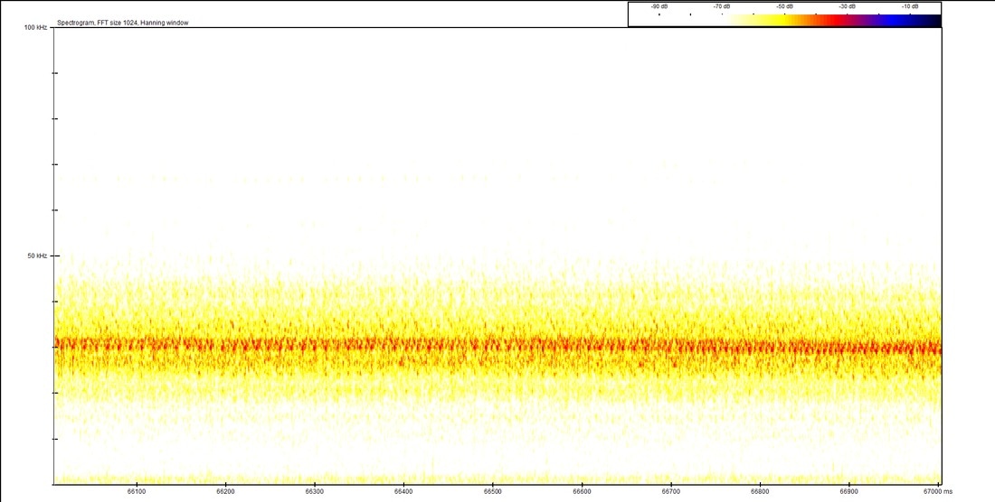
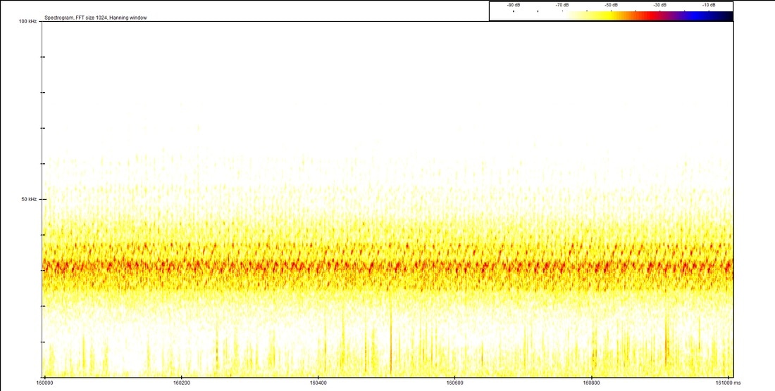
There is little difference between the two distances (although the 15cm does seem to be a bit quieter) but there is a distinct difference between the two detectors. The AudioMoth is particularly sensitive to moving air across the microphone resulting in extreme wind noise.
The noise levels on the Peersonic are significant but limited to a fairly narrow frequency which will still allow us to detect a number of bat species easily. It is also worth noting that the amount of noise varied through the flight, some louder and some quieter than the examples above. We're looking forward to getting into the field for some real world testing with this setup which we'll be doing next! After our initial field testing with the first bat plane (have a look at the blog post here) we knew that we needed to reduce the noise seen in the sonograms. This has been the driving force behind making the Mk2, Mk3 and purchasing the Talon. The noise is a product of the propeller spinning and as such we've tried to reduce the noise heard by the ultrasound detector by separating the propeller and detector by as much distance as possible. For the Talon we tested both the Peersonic and Soundtrap (which has changed name to Open Acoustic Devices due to a conflict of names - the actual detector is called the AudioMoth) detectors in a variety of positions to compare noise levels. The positions were:
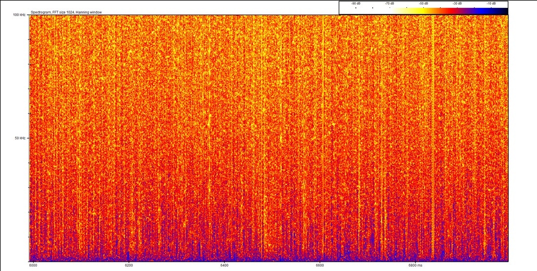
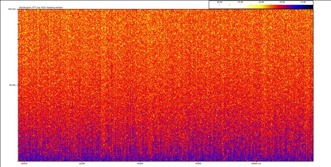
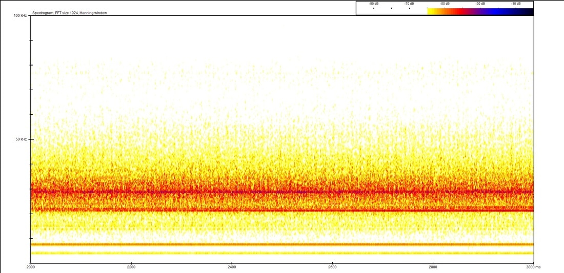
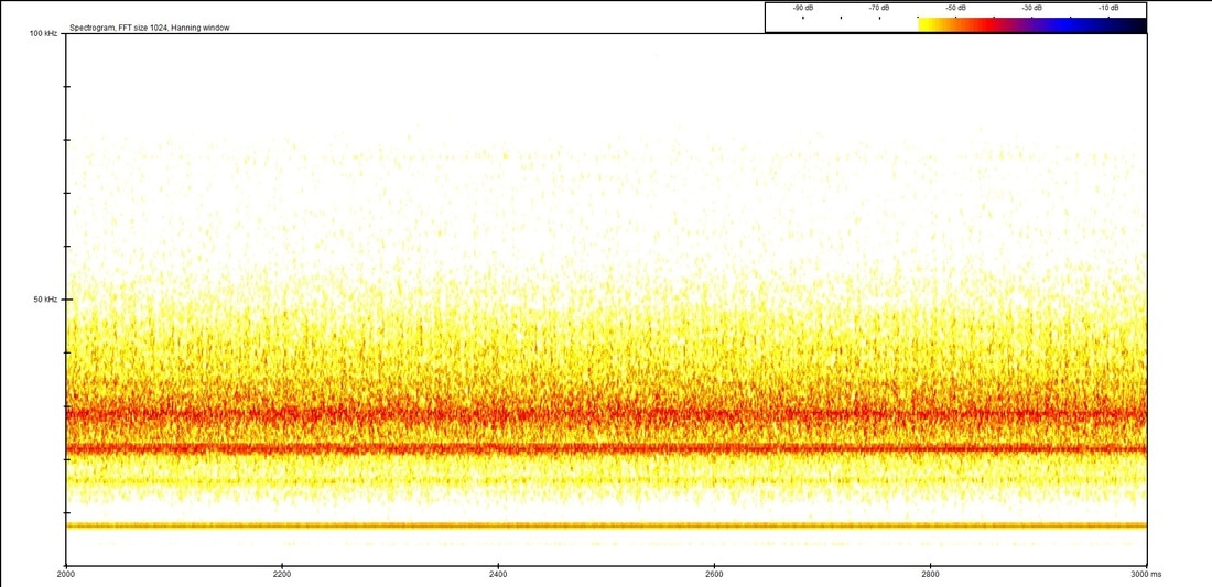
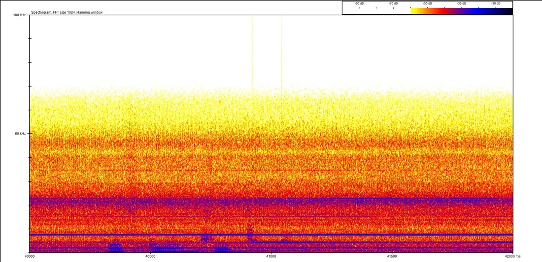
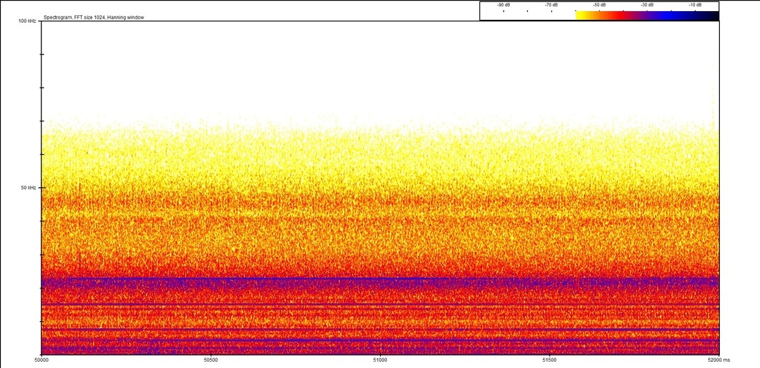
* This would be achieved by attaching an extension to the front of the plane. For fun we've called this the Nimrod option. It'll look something like the re-fueling pipe extending from the front of the plane: 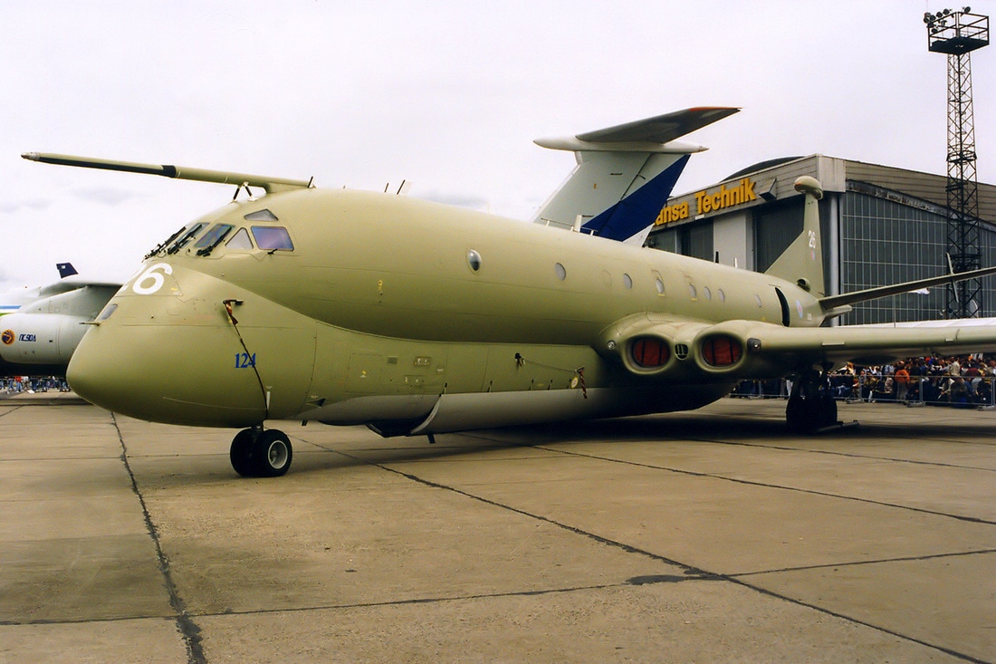 Let's take a look at the data we produced from the two detectors in the various positions. For reference, the throttle was set at the minimum value required for level flight (circa 35%) in order to minimise noise which mimics what we would do in field testing. Here are the sonograms:
The first noticable difference between the two detectors is that the Soundtrap picks up a lot more noise. There are a number of possible reasons for this. One we know will be a factor is that the Peersonic has a microphone which actively suppresses noise below 20kHz.
Looking at the difference between the various positions, it's apparent that the noisiest position is under the belly (also closest to the propeller) and the quietest is 5cm from the nose. The quietest is somewhat of a surprise, we expected the 15cm from the nose position to be quieter as it is further from the propeller. Perhaps this is due to the airframe blocking the sound at the 5cm position. In conclusion, the current thinking is to use the 5cm position for field testing. As there is still some time before the bats come out of hibernation we think it might be worth testing a further extended-Nimrod option, with the microphone circa 60cm from the nose and we'd also like to compare the signal to noise ratio for the Peersonic and Soundtrap (AudioMoth) in the preferred position using the ultrasound source (see the blog post here about using this previously). Keep checking out the blog for more! 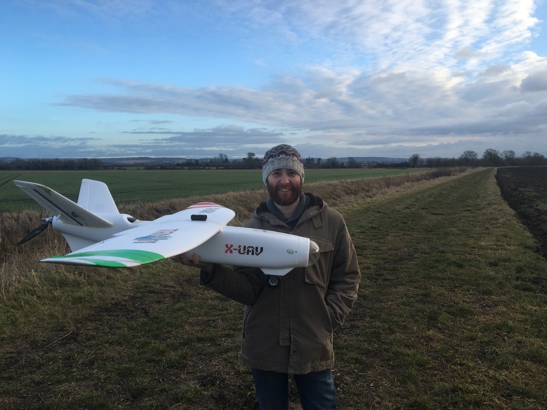 Tom A with our new plane - the X-UAV Talon Firstly, we'd like to give you a bit of background on why we're using the Talon at all: In mid-2016 we set about designing and building a plane which would fulfil our needs for the project, we called the new plane the Mk3 (see the post here). There were various goals we wanted to meet. We wanted to have a big wingspan so we can carry heavy batteries and fly for a long time and also increase the distance between the propeller and the detector in order to cut down on noise. During the build of the Mk3 plane we realised a couple of important points.
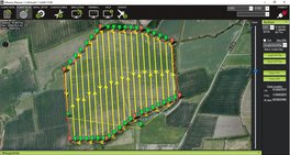
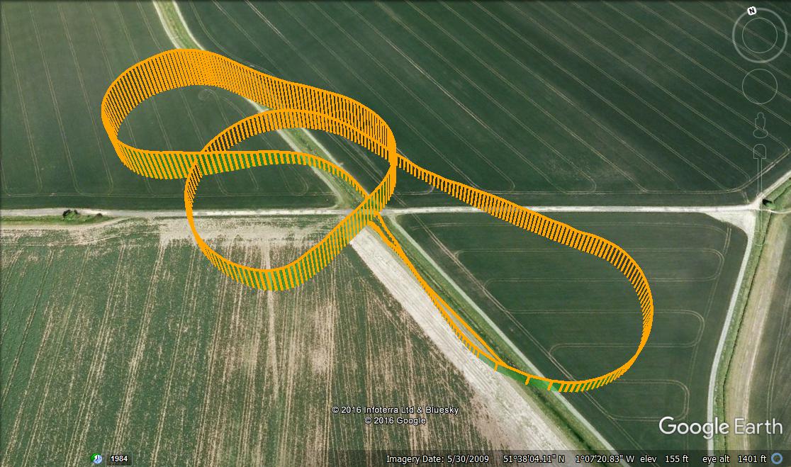
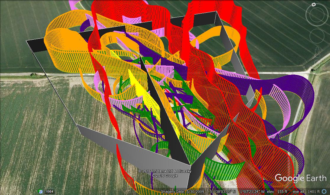
To further the aims of the project, it's more useful to find an off the shelf plane that people can pick up and put together themselves. That's where the X-UAV Talon comes in. X-UAV is actually a Chinese company that produces a number of UAV platforms, the Talon being one of these. The Talon itself is actually based on a Lockheed Martin design of a UAV called a Desert Hawk. The photo below shows the original Desert Hawk, quite a similar design to the Talon: 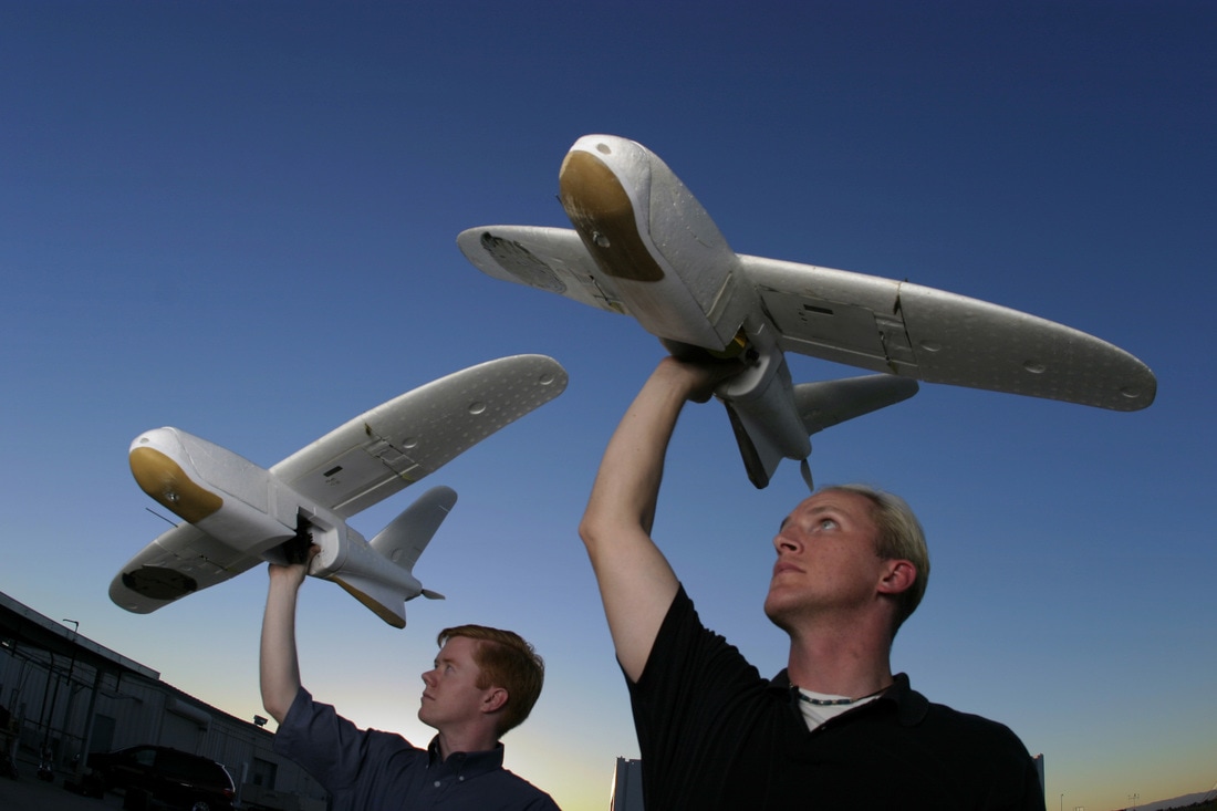 Lockhead Martin Desert Hawk I The Desert Hawk design was put together by Lockheed's famous Skunk Works division which is responsible for advanced projects and prototyping. They're some of the best aircraft designers in the world and have a back catalogue to prove it (U2, Blackbird, F-117 stealth fighter for example all started life at Skunk Works). There's also a wikipedia page about the Desert Hawk if you're interested. Given the history of the designers, we expected a good airframe. As a short aside, this is a nice re-purposing of the word drone from a military context into a more environmental/ecology context or to put it another way into a more humanitarian context. Drones can be viewed as tools like any other and although the initial use of these tools was often by the military, it's increasingly common to see commercial and hobby drones which may help to re-purpose the word itself. Back to the Talon and happily, it does fly brilliantly and we're really pleased with its characteristics in the air. The airframe is a very smooth flyer and we're looking forward to investigating potential placements of the ultrasound recorder so we can get out for some field testing. Below we've shown a couple of images taken from the telemetry on board showing the flight path. The one on the left is the maiden flight and the one on the right shows all the test flights performed:
For interest here's a video demonstrating some of the test flying: If you're interested in potentially building your own bat sensing drone and the more technical aspects of the project then we're going to cover the components of the Talon and a comparison between the Talon and the Mk3 next. If you're not interested in the more technical aspects of the project below then know that the Talon files well and meets the needs of the project so we'll be using it a lot more in the future! The Talon is essentially meant to act as an easy to build replacement for the Mk3 plane. As such, it would be useful to provide a quick comparison between the two:
The most useful figures we're looking at are the wing loading and the cubic wing loading as because the two aircraft are similar in size these can be compared. The numbers are close enough to tell us that the two planes will have similar stall, cruise and landing speeds (though a variety of other factors also come into play here). In practice this has also turned out to be the case. A lower wing loading means that the wing needs to generate less lift for the plane to stay in the air and hence it can fly slower (which is good for slow landing speeds and cruise speeds). There are wing extensions available for the Talon though they have been difficult to find. We've luckily just managed to find some and they're 'winging' their way (it's the best I could come up with at short notice) over here from China as I type this. They'll increase the wing area and reduce the loading to around 16.6 oz ft^-2 which will aid slower flight. Finally, if you want to be able to reproduce what we've done then it would be useful to cover all of the bits and pieces that have gone into the Talon. Have a look at the table below for the full specification:
* We bought the Pixhawk 1 quite some time ago (in 2014) from 3DR. Since then they have stopped selling flight controllers and have moved onto closed systems. There are a couple of options available. A group of people who worked on the original Pixhawk 1 have launched a successor, called the Pixhawk 2.1. This would be the preferred option as it's a better flight controller. The second option is that because the Pixhawk 1 was open source there are a variety of clones which perform in exactly the same way. This would be less expensive and provide the necessary functionality. It's worth having a google for which are the best clones if you decide to go down this route.
*2 The original power module (this is the part which connects the main battery to power the Pixhawk) only accepts up to 4S batteries. As we're using 6S we needed a new one which could accommodate the higher voltage. If you do decide that you'd like to go ahead and build a bat drone then do get in touch with us as we'd be happy to offer any advice. Our email is on the contact us page. Next, we'll be posting about some acoustic testing with the Talon, watch this space! There was a little time between Christmas and New Year when it was possible to nip out for a test flight of a new trainer plane. The trainer is exactly as it sounds: a plane to aid the training of new pilots. This would potentially help both of us (Tom M and Tom A) to be able to fly and aid the training of others who wanted to invest in their very own bat drones (we're not aiming to sell anything but we can help people with building aircraft or provide advice on what to buy). It's worth pointing out that we would always recommend that people start out with a simulator on a computer and then move onto a trainer plane. The first plane that we flew, the Bix 3, is actually a trainer. Check out one of our first blog posts here to see more about it. There was a little spare foamboard left over after the build of the Mark 3 plane so we thought it would be useful to build a trainer aircraft with it. The maiden flight of the plane was successful in that the plane landed in one piece. However, the weight of the plane is quite high relative to the wing area leading to a high wing loading and therefore relatively high cruise speed. This doesn't make for a perfect trainer and a lighter plane would be more desirable (either bought or built). The design used was one from experimental airlines on Youtube; have a look at their channel here if you're interested. It was discovered recently that the foam we're using is circa 2.5x heavier than the foam experimental airlines uses which has lead to heavier than expected aircraft. There's not many photos of the completed plane unfortunately so here's one of the better ones: 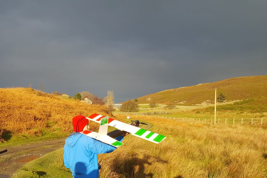 And, getting to the bit where it all went wrong, take a look at the video below: So at least we know what the issue was and have learnt a lesson or two.
For a trainer we'll probably fix up one of the Bix 3's that we've been using as these are light and fly well. When building further aircraft we'll use lighter foamboard. There's some available on Hobby King which is even lighter than the experimental airlines foamboard so this seems like a good option. And finally, we'll not fly too far away from our transmitter without an autopilot failsafe in place! The flight controller for this plane doesn't have the ability to return to launch so this was not an option in this case. Next up, we'll be test flying a new airframe - the Talon! Watch this space.... Following on from our less than successful weekend of testing (check out the blog post here if you haven't seen it already) we decided to build a better plane. In this post we're going to cover a bit about what we wanted the air frame to achieve along with a description of how the major bits were built and finally the maiden flight. This is partially to keep you up to date with what we've been up to and partially to pass on the information required to reproduce what we've made. Design parameters / goals:
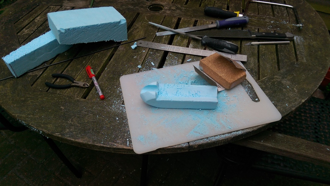
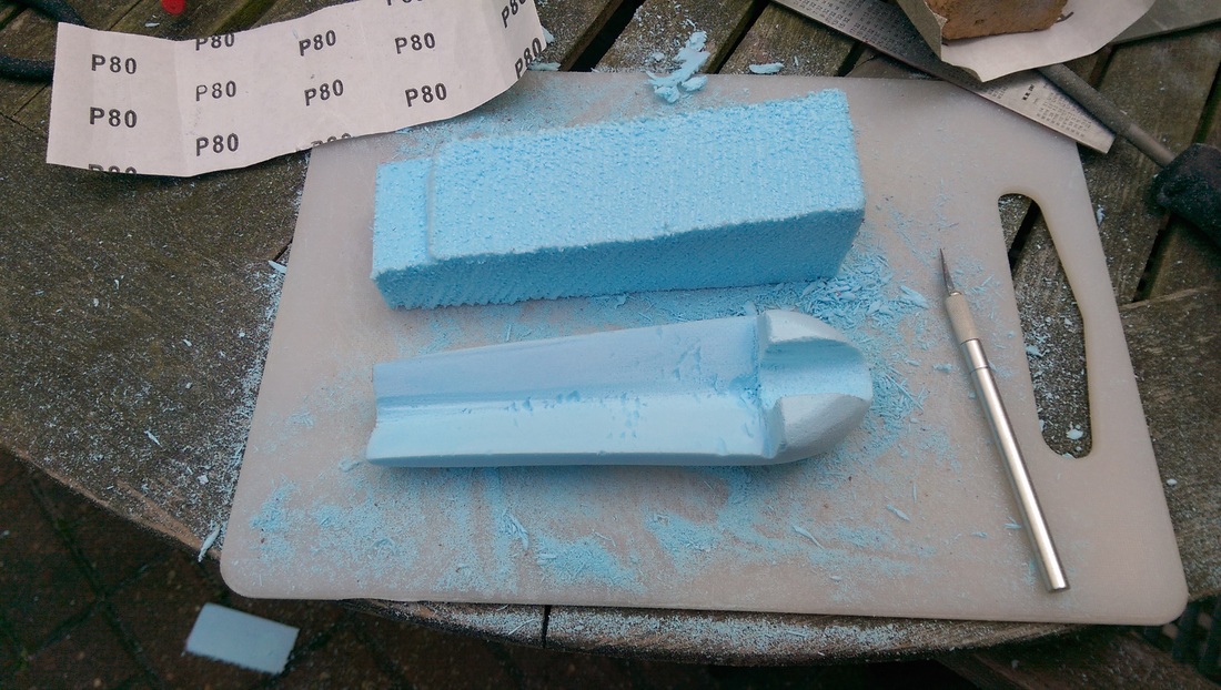
With the above parameters in mind a rough 3D model was designed: 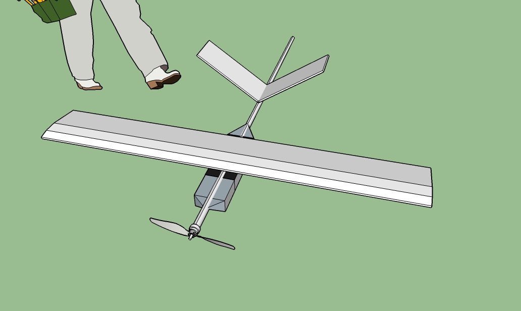 The model shown above has a wingspan of 2m and a chord (the distance from the leading edge to the trailing edge of the wing) of 30cm which provides a wing area of 60dm2 (6000cm2). Generally, the larger the wing, the more lift it can produce which for our use is a good thing. The 'fuselage' or at least the bit that joins all the pieces together is made of a carbon/glass composite fishing rod as seen in the Mk2 design. It's collapsible which was a necessity of the design as it wouldn't fit in the car otherwise! The weight was estimated to be around 2.5kg and this was factored into the power system choice. Power system In order to achieve a long flight time the current draw from the battery would need to be low so a relatively high voltage system was chosen. The battery is a 6S LiPo (though Li-ion would also be suitable), the motor is a Tiger MN4014 400KV and the prop is an aeronaut 15x6 folding. It's estimated that this setup will produce circa 3-3.5kg of thrust (greater than a 1:1 thrust to weight ratio) and cruise at about a 5A draw. If we had a 5000 mAh battery and used up all the juice (which you shouldn't do as for maximum longevity and battery health you should always use only up to 80% of the capacity) then this set up would theoretically fly for 1 hour. The motor was supplied at reduced cost by Duncan at heliguy.com and a big thanks goes out for that. The prop and yolk (along with ESC and a few other bits and pieces) were supplied by Gareth at Gliders.uk.com at a reduced cost so a big thank you to him as well. In case you were wondering, the prop is folding so we can protect it upon landing. Previously we had a number of issues in breaking props and motor shafts so hopefully this will cut down on those! Here's a quick look at the motor and folding prop: 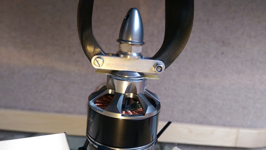 Bat plane Mk3 MN4014 motor and folding 15x6 propeller After a discussion with a local flying club (special thanks to Steve and all at Ham FC) it was decided that it would be better to place the motor at the rear of the aircraft in order to put the microphone into clean air and away from the prop wash. Building technique and materials The main considerations here were cost and ease of use in building. Given that we have limited experience of building planes the construction techniques needed to be simple and effective. Fortunately there's a lot of information about simple building techniques online and especially on YouTube. There's a great channel called experimental airlines which provided most of the building techniques used in the construction. Specifically it's worth checking out the videos for the Armin wing and carbon-fibre tail booms. Wing construction The material for the wing and tail surfaces is Kapa foamboard which is an expanded foam sandwiched between cardboard. We've been brilliantly supported by modelshop.co.uk who have supplied all the foam and a fair few other bits required for the build. Special mention to Andy there who's been incredible. The wing stiffness is partially provided by a 2m carbon fibre spar which runs the length of the wing and is held in place using foamboard 'formers' which help create the aerofoil shape of the wing. All the carbon fibre used the build was supplied at a reduced cost by easycomposites.co.uk so a big thank you to them. Below is a photo of the wing mid-build showing the foamboard formers in place. The carbon tube is in the groove between the foamboard. As a weight saving technique holes were drilled in the foamboard which can be seen in the photo. 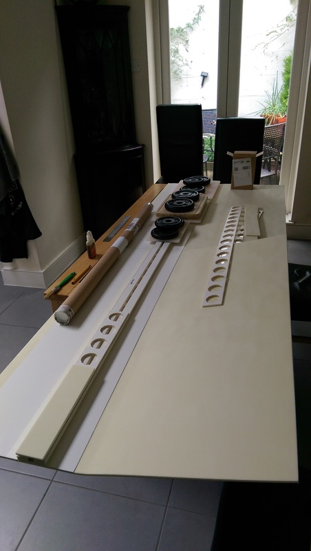 Bat plane Mk3 wing mid- construction After a bit of gluing, sanding and taping, the result was a wing that measured 2m x 30cm along with a further 5.5cm of control surfaces. Both ailerons and flaps were made out of the foam and covered in packing tape to waterproof them and provide some structural strength. The wing has a flat bottomed aerofoil section with a rough 15% height to chord ratio which should provide relatively high lift. Here's the completed wing laying on top of the fuselage and v-tail section: 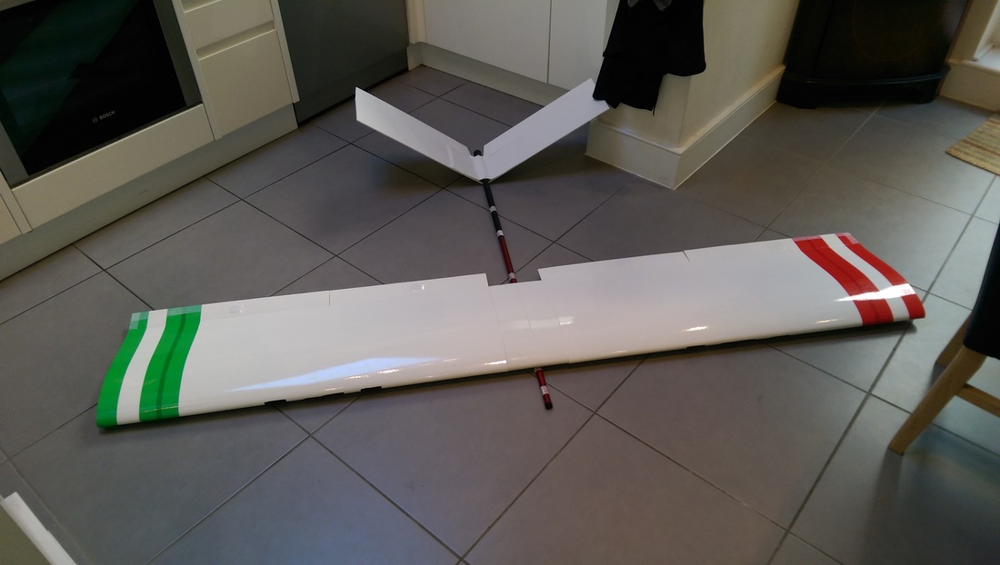 Bat plane Mk3 - completed wing The next matter to attend to was how to attach the wing to the fuselage. The answer to this was handily provided by the Experimental Airlines YouTube channel in their carbon tail boom video. This technique uses a sheet of carbon fibre/glass fibre/metal attached to the boom (fuselage) and elastic bands to hold the wing in place. Although the elastic bands provide an excellent form of damage limitation in the event of a crash (see the video linked above); we weren't 100% convinced that they alone would be sufficient to attach the wing to the carbon sheet. So, we used a couple of carbon strips and nylon nuts and bolts to attach the wing to the sheet in addition to the elastic bands. The carbon we used was actually a carbon/glass composite (as it is about half the cost of a pure carbon sheet). It comes with one side not covered in pre-cured resin so as part of the build we covered this in resin to ensure we weren't going to pick up any splinters in use. Here's a photo of the drying carbon: 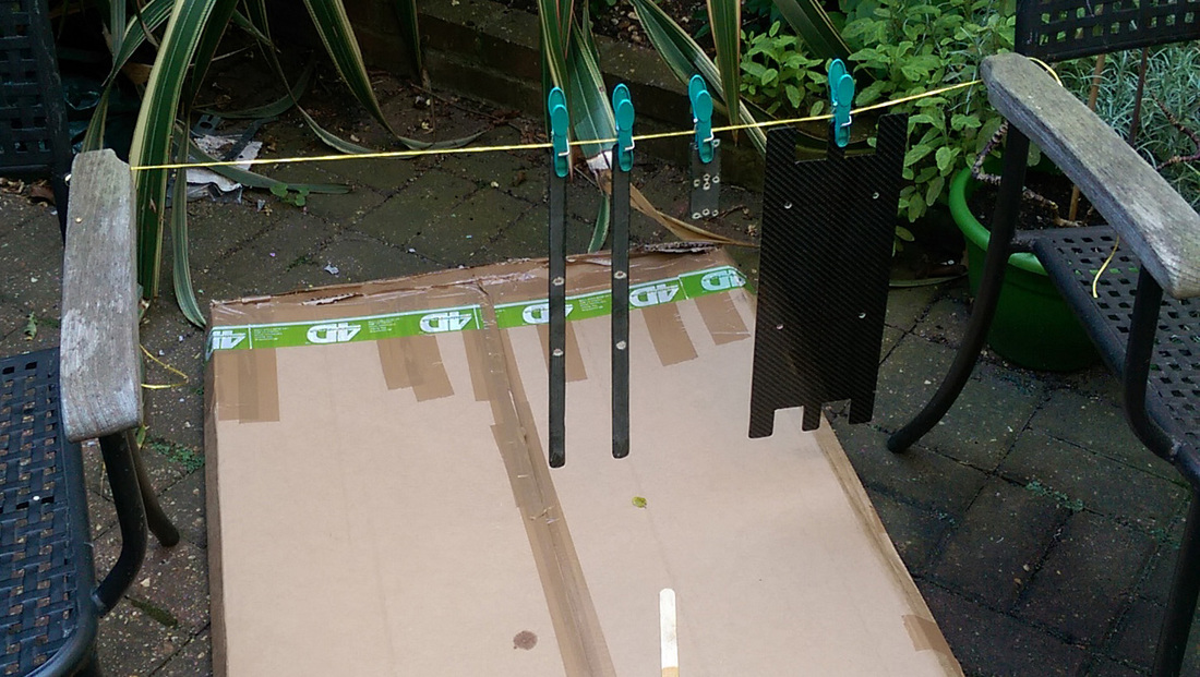 Carbon fibre sheets with resin applied drying outside And below is the intended structure of how it'll look without the wings in situ. Note that the two parallel strips will be inside the wings. 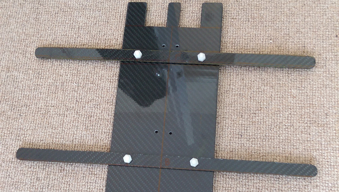 Completed wing attachment assembly Finally, below is how the wing looks with the wing attachment assembly in place. Hopefully it makes sense for how the elastic bands fit over the tabs on the large carbon sheet which is attached to the fuselage. 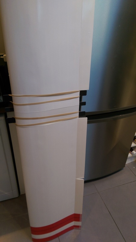 Wing and wing attachment assembly in place So that's one major part of the construction completed. Once the v-tail was constructed, the large carbon sheet that the wing sits on was then glued to the fuselage along with a couple of small diameter (approx 5mm) carbon tubes to hold it in place and finally secured with a couple of cable ties. V-tail construction Prior to any of the building actually taking place a few numbers were worked out to ensure the plane would have a fair chance of firstly flying and secondly being able to be controlled in the air. Part of this is working out the size of the tail and a couple of numbers called the horizontal and vertical tail volume coefficients. These are just formulas which you plug your numbers into and they tell you whether the tail will be able to provide the stability that its meant to. To calculate the v-tail area and angle we used Dr Mark Drela's formulas here. He's a professor in the Department of Aeronautics and Astronautics at MIT so seems to be a pretty reliable source! We also used a value of 20% of the wing area for the 'horizontal' stabiliser and 10% of the wing area for the vertical stabiliser. The horizontal and vertical tail volume coefficients (Vh and Vv) were calculated as 0.41 and 0.031 which are satisfactory but not brilliant. There is a restriction on the placement of the v-tail as the fuselage telescopes in the middle so the tail and wings can only be placed on one half of the fuselage (over a distance of about 1m). If we could have used a non-telescoping tube for the fuselage then we could have distanced the wing and tail more which would have resulted in a better Vh and Vv. We'd worked out that our v-tail would therefore be 20cm x 45cm and have an angle of 110 degrees between the tails (ie 35 degrees from horizontal each). Now all we needed was a method to attach the tail to the fuselage. Quite a few ideas were brainstormed and although some would have provided more strength than the one that was chosen it's a trade off between weight and strength so weight was prioritised. A number of ideas involved carbon tubes going through the fuselage which was also not practical in our case as this would have meant a fuselage which could not telescope. The idea we settled on was to attach two carbon strips to the fuselage at the required angle and have a single section of foam forming the two tails which would be glued to the bottom of the strips and the fuselage. Another layer of foam was then placed over the strips and tails and glued in place to provide further security. Here's the carbon strips being glued in place: 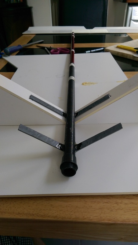 V-tail attachment There's no close-up images of the tail currently but what we do have is an image of a previous attempt to glue the tail in place that wasn't successful. It gives you an idea of how the tail attached to the fuselage and carbon strips, or rather in this case, how it didn't. 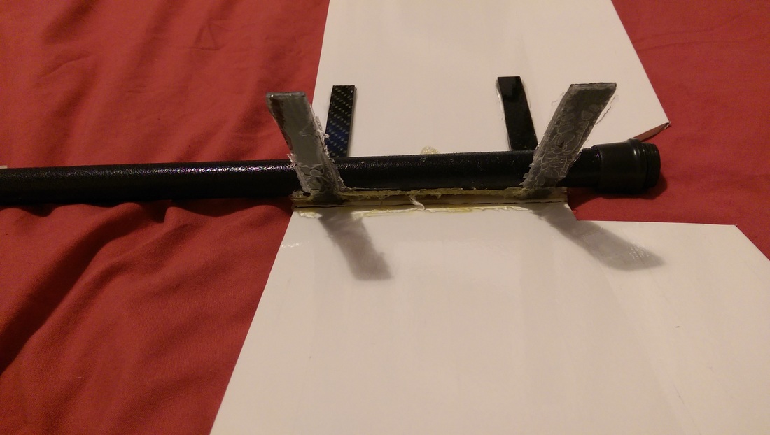 V-tail attachment failure The issue was that the tail is covered in packing tape which helps protect it from the elements (well, just water really) and also provides a bit of structural strength. The glue used on the carbon strips didn't adhere well to the tape and when it was placed down quite hard it simply popped off. This does give an idea on how the tail is attached to the fuselage though. The issue was fixed by removing the packing tape and cardboard underneath so that the carbon strips attach directly to the foam in the foamboard which provides a much stronger adhesion. The control servos for the v-tail ruddervators (a mixture of elevator and rudder) were initially placed on the fuselage just behind the wing and long control rods and carbon tube guides used. After experimenting with this it was decided that the control rods were flexing too much and this would lead to poor modulation of the control of the surfaces. The servos were then moved to a direct placement on the tails and a much shorter control rod used resulting in a satisfactory setup. To pod or not to pod In the initial design shown in the 3D model at the top of the page there's a pod attached to the bottom of the fuselage. This was intended to hold all of the electronics equipment (including the detector) and the battery and also to act as a form of landing skid. The final design of the plane doesn't incorporate this pod as it was realised that the majority of the electronics could fit within the free space of the wing with the battery and detector then being external. This was worked out as during the build the bits and pieces being used and constructed were weighed and it turns out that foamboard is actually quite heavy! The initial thoughts on the weight were that it would not be over 2.5kg but this turned out to be unrealistic when using foamboard due to its weight. Given that the battery alone weights 960g perhaps 2.5kg was an unrealistic goal for a plane of this size. The final weight of the plane is circa 3.7kg which did lead to some concerns over whether it would actually get in the air! The lack of a pod also lead to one other concern: Landing gear The plane doesn't have any landing gear to speak of and instead relies on skids and a slow landing speed. The skids are there to protect the wing attachment assembly and the v-tail attachment assembly and motor. They are constructed of a high density foam (not sure what its real name is but in the RC world it's called blue foam). Here's a couple of images taken during the construction of the skids:
Essentially the foam was cut with a saw and then filed and sanded into a vague aerodynamic shape. It was then glued with Gorilla glue to the fuselage: 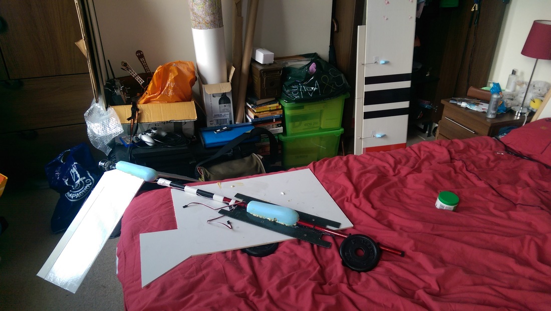 Fuselage with landing skids attached Although the skids would provide some protection for the wing and tail attachment assemblies it's very likely that the wing will strike the ground upon landing. This isn't an ideal solution but the foamboard is flexible and should be able to cope with this. It's also easily replaceable should it tear or break. The main factor to limit any potential damage during landings is to have a slow ground speed. Also worth noting in the above image is the wing in the background and the small pieces of blue foam used to protect the servo arms and control rods for the wing control surfaces. The servos are buried in the wing with only the arms sticking out so these are the only bits which require any protection. The brains of the plane - the flight controller The final piece of the plane is the bit that's actually going to do most of the flying for us, the flight controller. We're sticking with the Pixhawk flight controller from 3D Robotics in the US as it's a tried and tested board and one we're very familiar with from our other testing. There was a little bit of additional set up required using the built in v-tail mixer for the Pixhawk and with the addition of flaps but aside from this it was quite straight forward to get going. There was an issue with the compass being affected by magnets which were used to keep the wing opening closed but once these were removed we were good to go! Below is the Pixhawk being configured and tested on the wing. You can also see the v-tail attachment in this image as well as the tail servo placements. You might also notice that we've got Mission Planner loaded up on a laptop. The laptop was kindly provided by a mutual friend, Mike Davis, so we'd like to take this opportunity to give him a big thank you as well, thanks Mike! 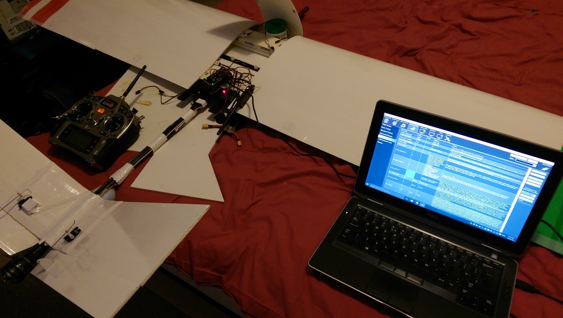 With the plane now completed all that was left to do was to test whether it actually flies! The construction of the Mk3 was done in London at Tom M's house so the first test would be whether it actually fits in Tom A's car! Happily it fitted with a few cm to spare though we still managed to crush the end of one of the ailerons in the boot lid. Fortunately it straightened out to nearly new once we had it out of the car in Oxfordshire where we do all of our flight testing. Maiden flight We really had no idea whether the plane was going to fly as although all the numbers looked ok the real test is in the field! The major concerns were over the weight (as this was much higher than anticipated) and whether the motor would be able to put out enough thrust to generate lift quickly enough in order to fly. There was also a little concern over the flexibility of the foamboard for the control surfaces as they are quite long. Here's what happened (you'll probably get a clue from the thumbnail!): It worked!!!
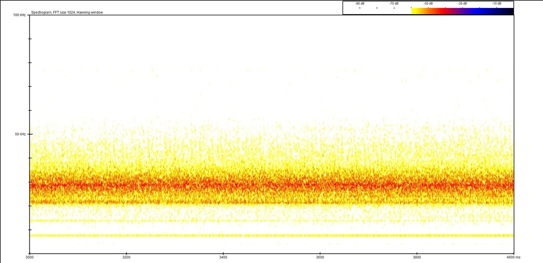
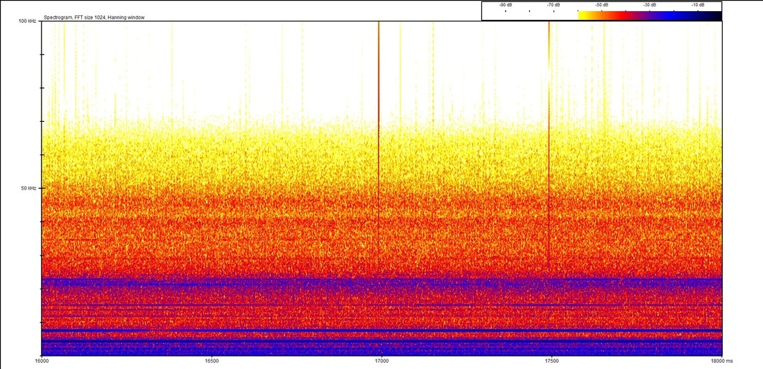
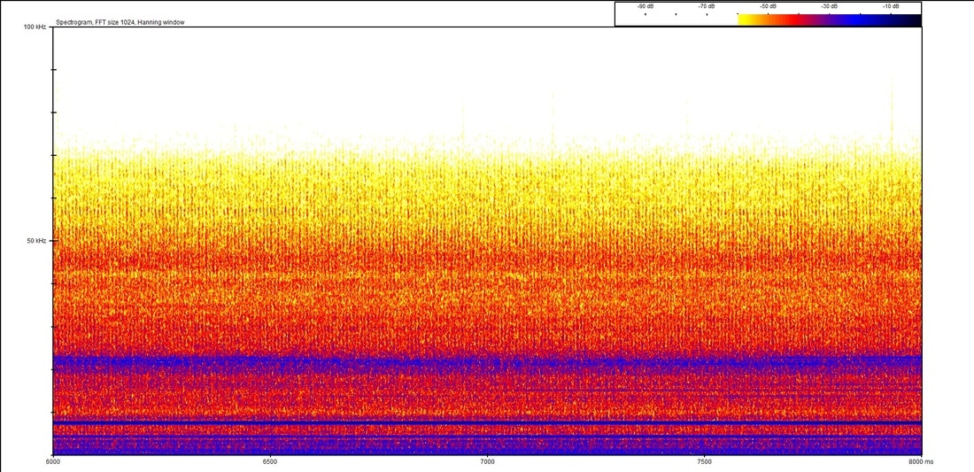
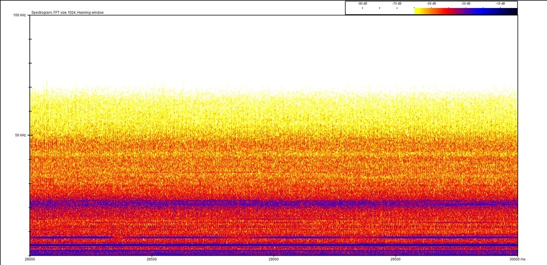
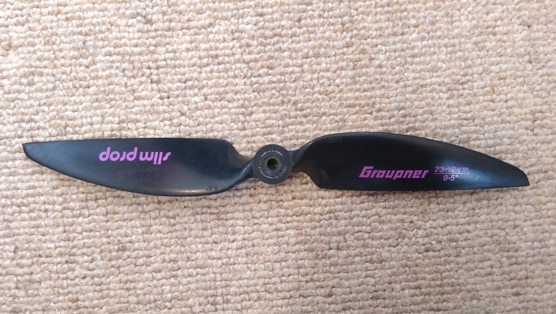
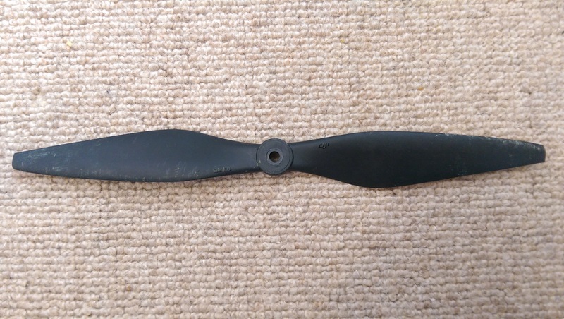
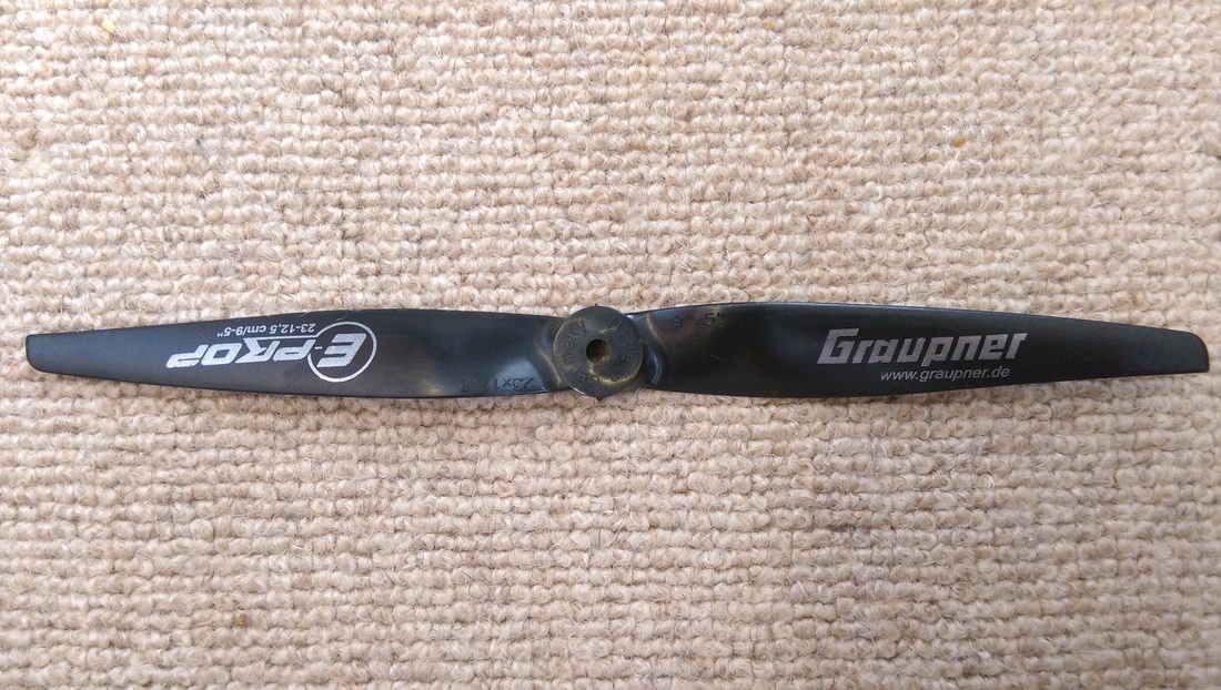
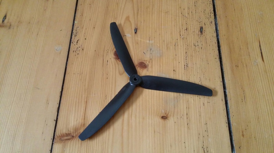
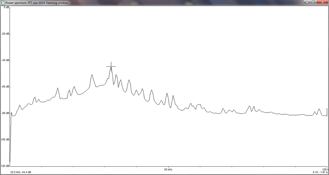
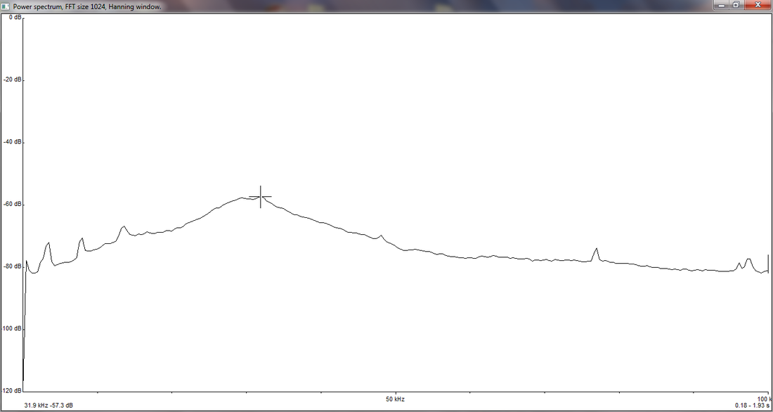
Tom A was doing the throwing with Tom M standing behind at the controls. As you might be able to tell from the video it had no problem in taking off and the prop was generating more than enough thrust to propel it into the air no problem. Tom A actually mentioned that it's almost a case of holding it back. The first flight was all with mid-flaps and the flaps were then tested during the second flight. The landing with full flaps was nice and slow and no damage was done to the plane. It was also noticed that elevator authority could be a little better so this will be dealt with prior to the next round of testing. In general though the flights went brilliantly and the plane was stable in the air and controllable which is exactly what we're looking for. We're really happy with the result. The additional weight of the plane is also advantageous for windy conditions which we tend to get a lot of in the UK so at least there is a benefit to this. The next step is to go through some auto-pilot testing and ensure the plane can fly autonomously and then do some surveys! As always, watch this space! The last time we flew the plane we pretty much smashed up everything but there was just enough left to test a new set of propellers that we got. There's no photo of the DJI q-tip prop unfortunately but if you imagine the DJI prop with about 5mm of the tips turned 90 degrees into the flow of the air then this is what it looks like! We tested each propeller for the amount of ultrasound that it gave off and here are the results. The axis along the bottom is the frequency and up the side is the volume, so we want the blade with the lowest peak.
Top left - clockwise: 3 blade, DJI normal, DJI with q-tip, Graupner eprop, below: Graupner slow fly 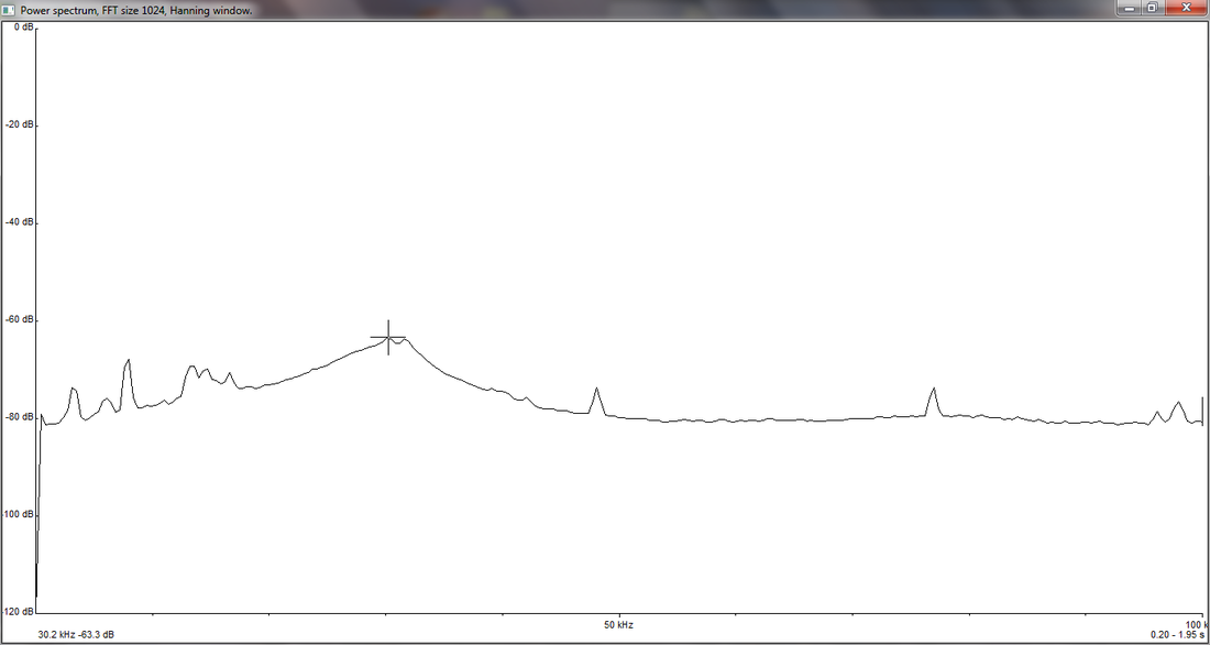 The Graupner slow fly propeller, above, (which is wider than the other propellers) was much quieter than the other props. In fact, since the volume is measured on a log scale (decibels) this propeller was 10 times quieter than the loudest prop - the three-bladed propeller.
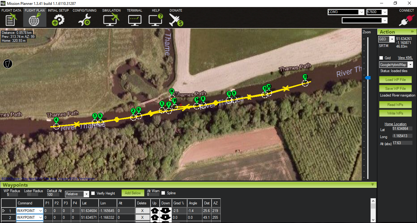
This test demonstrates that the propeller in use does have a significant affect on the amount of ultrasound produced and that is is possible to reduce the ultrasound interference from this source. We always knew there would be ups and downs during this project and a couple of weekends ago we certainly experienced some downs. It all started out well, having been in touch with the University of Oxford we were able to use our plane to do some testing in Wytham Woods. Wytham is a small village north west of Oxford and the woods there are a site of specific scientific interest (SSSI) and as such are in use for a large number of research projects by the University. Our plan was to fly a circuit on the inside of a number of tree lines and see if we can record anything. The motor shaft of the Mk2 plane unfortunately broke during it's last flight (see the landing in the video) so we decided to use the Mk1 plane (the Bix3) and attach a composite tube on the underside at the back of the plane to increase the distance from the propeller to the microphone.  Tom M setting up The first flight using the stabilisation and auto-leveling on the flight controller (FBWA mode) went well and we were happy to go ahead and load up the waypoints and set off on an autonomous mission. Below is what we actually flew although the auto section (in blue) doesn't show accurate altitude. During the auto section of the flight the plane was actually increasing in speed and losing altitude. You might be able to make out the little plane models that are on the flight lines - these show the attitude of the plane. 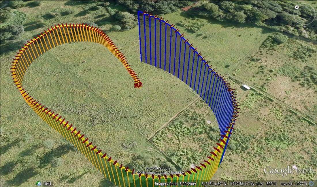 Telemetry from the Wytham crash Unfortunately, the plane impacted the ground at the end of the auto line. It was a pretty hard crash and I'm sorry to say we don't have any photos as we were quite disappointed at the time and didn't think of this. As a brief description, the battery was found approximately 30 feet away (it was placed externally on the plane for CG control); the motor had unattached from its housing and the propeller had chewed through the flap and a part of the left wing before impacting the ground and breaking in several places (the only part of the prop left on the motor was the hub); the wings had also unattached from each other and broken their connectors to the fuselage; the fuselage itself was cracked in several places. So, this wasn't exactly ideal and to compound this, we had no idea why the plane crashed which was probably the major concern. After discussion with the programmers of the flight control firmware we discovered that the plane didn't have enough elevator authority to correct its descent and needed the PID settings to be updated. After a fair bit of time spent gluing small bits of EPO together we think the plane should fly again! This all happened on our first night of a weekend of testing. We still had a couple of days to try and get something flying so we moved onto using the Mk2 plane and testing this with a new motor. 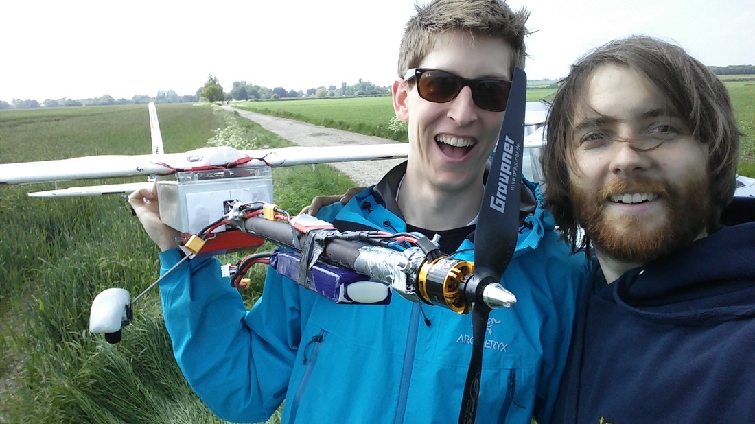 The Mk2 ready for a test flight! Using a set up of a 4S battery on the Mk2 we were able to fly a test fight of the plane, fully loaded with the bat detector and landing gear (to help protect the motor and prop).
However, our costly weekend wasn't about to stop there and we discovered that when we used the 3S battery the prop just wasn't able to generate enough thrust for level flight and we floated down for fairly gentle landings. Given that we're already stressing the motor more than we should by using a 4S battery it's just not the right set up to fly the weight that we want to. The Bix3 wing that we're using isn't designed to fly with the wing loading we're putting on it. As our power system also isn't able to generate enough thrust we've decided that the current design of the Mk2 is not suitable for our needs. What we're therefore decided is we need a new plane that can support the larger flying weights we require (circa 3 kg). So, we're in the process of designing and building a Mk3 plane which should fit our needs really well! Keep your eyes on the blog for some specs and 3D models of what we're looking to build! After an initial successful flight to prove the wings would stay on and the plane doesn't generally disintegrate in flight we've been able to fly the MkII again and are happy with the results. 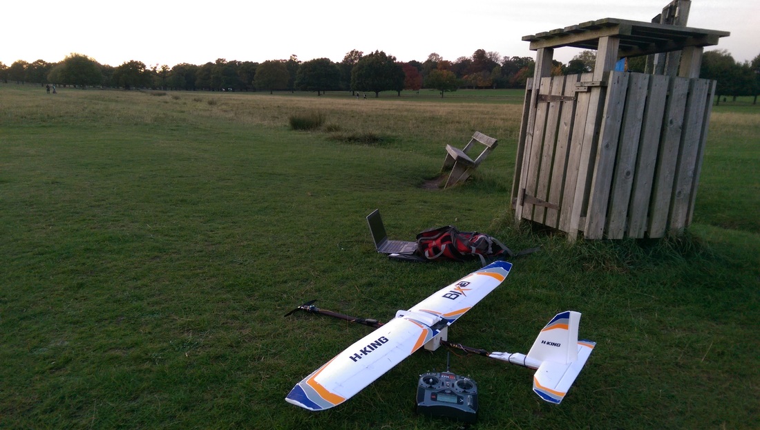 We wanted to test two things:
Check out our video of the MkII in flight below... Ultrasonic interference It was our plan to test this in flight but unfortunately we weren't able to do this as in our last flight we snapped our motor shaft (which holds the propeller) from the plane which means we'll have to fix this before more flying (and add some landing gear!). Fortunately, we did take some readings on the ground at approximately 50% throttle (which keeps the plane level). Peter at Peersonic has kindly provided us with a new microphone to test which discriminates against 8kHz and below. We tested the new and standard mics at the full fuselage extension with the mic facing perpendicular to the fuselage. Original Microphone 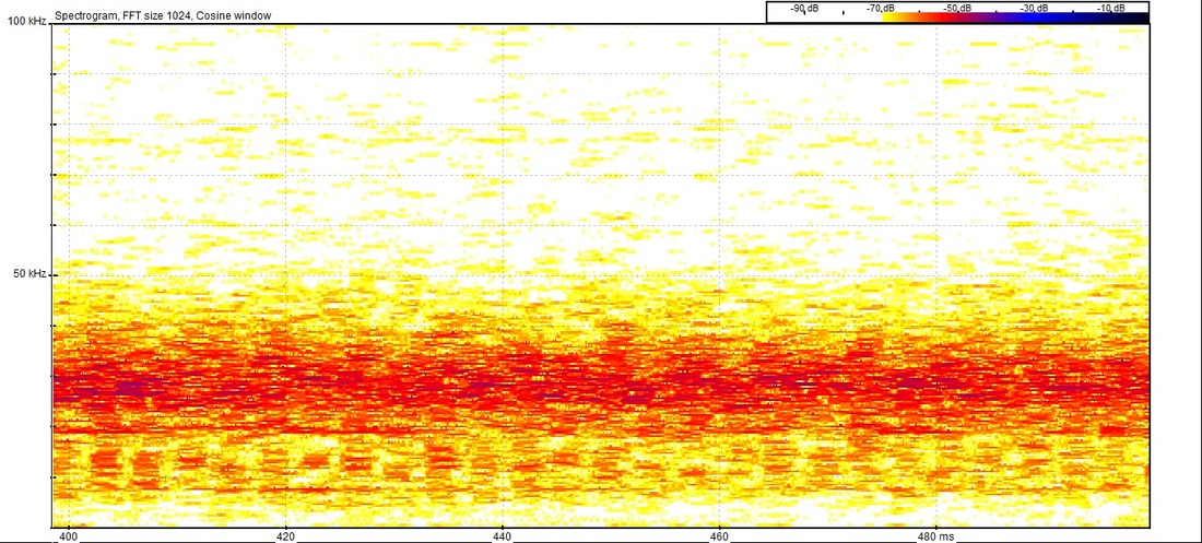 New Microphone 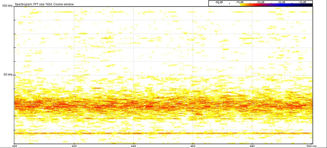 What do the results tell us? We can compare these two recordings with audio from the previous plane model. In this image we have the images above on the left and right respectively and a recording from the previous plane in the centre. Clearly the new plane design reduces the amount of noise by putting more distance between the microphone and propeller. 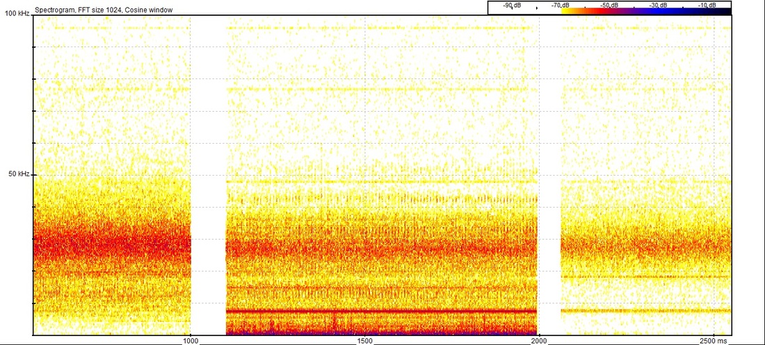 Hopefully with this new setup we'll have more chance of spotting bat calls in our sonograms. Real world testing to follow! Although it's been a little quiet over winter we've had a new part of the project to work on: the Mark II plane!  Bat UAV Mk II We had a problem with our Bix 3 based Bat UAV as a lot of ultrasound interference was coming from the propeller of the plane. This was picked up because the microphone is about 70 cm from the propeller.
By moving the microphone further away (to approximately 2 m) from the propeller we expect to see a vast reduction in ultrasound noise originating from this source. The logical way to do this was to put the motor and propeller at the front or back of the plane and the microphone at the opposite end. Using an extending telescopic fishing pole as a fuselage we're added some wings and control surfaces and managed to do just that. The photo above is of the plane without the full length of fuselage. In this configuration it did well in it's first test flight and we're planning on getting more testing in soon. Next time, we'll be testing the flight at the full length of the fuselage and then with the detector attached. Watch this space! |
Categories
All
Archives
March 2017
|


 RSS Feed
